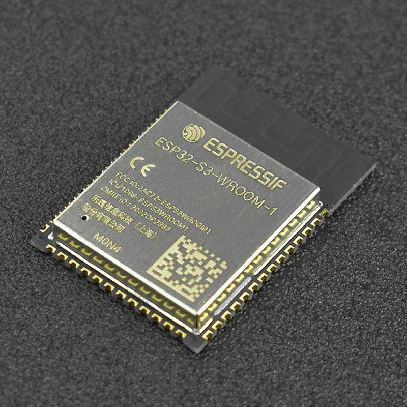
ESP32-S3-WROOM-1-N4 Module (PCB Antenna)
The ESP32-S3-WROOM-1 is a powerful, generic Wi-Fi+ Bluetooth LE MCU module built around the ESP32-S3 series of SoCs.
On top of a rich set of peripherals, the acceleration for neural network computing and signal processing workloads provided by the SoC makes the module an ideal choice for a wide variety of application scenarios related to Artificial Intelligence of Things (AIoT), such as wake word detection, speech commands recognition, face detection, and recognition, smart home, smart appliances, smart control panel, smart speaker and more.
The ESP32-S3 integrates multiple peripherals including SPI, LCD, Camera interface, UART, I2C, I2S, IR remote control, pulse counter, LED PWM, USB Serial/JTAG controller, MCPWM, SDIO host, GDMA, TWAI® controller (compatible with ISO 11898-1), ADC, touch sensor, temperature sensor, timers, and watchdogs, as well as up to 36 GPIOs. It also includes a full-speed USB 1.1 On-The-Go (OTG) interface to enable USB communication.
Features
- Powerful and generic Wi-Fi and Bluetooth
- Integrates multiple peripherals
Specifications
- ESP32-S3 series of SoCs embedded, Xtensa® dual-core 32-bit LX7 microprocessor (support single-precision floating-point units), support the clock frequency of up to 240MHz
- 384 KB ROM
- 512 KB SRAM
- 16 KB RTC SRAM
- 4 MB SPI flash
- Bluetooth LE: Bluetooth 5, Bluetooth mesh
- 40MHz crystal oscillator
- Module Dimension: 18×25.5×3.1(mm)/0.71×1.00×0.12(inches)
- Operating Temperature: –40~85℃
Package Contents
- 1x ESP32-S3-WROOM-1-N4 Module (PCB Antenna)
Resources
- ESP32 S3 WROOM-1 Datasheet
Pinout
| Name | NO. | Type | Function |
| GND | 1 | P | GND |
| 3V3 | 2 | P | Power supply |
| EN | 3 | I | High level: on, enables the chip Low level: off, the chip powers off Note: Do not leave the EN pin floating |
| IO4 | 4 | I/O/T | RTC_GPIO4, GPIO4, TOUCH4, ADC1_CH3 |
| IO5 | 5 | I/O/T | RTC_GPIO5, GPIO5, TOUCH5, ADC1_CH4 |
| IO6 | 6 | I/O/T | RTC_GPIO6, GPIO6, TOUCH6, ADC1_CH5 |
| IO7 | 7 | I/O/T | RTC_GPIO7, GPIO7, TOUCH7, ADC1_CH6 |
| IO15 | 8 | I/O/T | RTC_GPIO15, GPIO15, U0RTS, ADC2_CH4, XTAL_32K_P |
| IO16 | 9 | I/O/T | RTC_GPIO16, GPIO16, U0CTS, ADC2_CH5, XTAL_32K_N |
| IO17 | 10 | I/O/T | RTC_GPIO17, GPIO17, U1TXD, ADC2_CH6 |
| IO18 | 11 | I/O/T | RTC_GPIO18, GPIO18, U1RXD, ADC2_CH7, CLK_OUT3 |
| IO8 | 12 | I/O/T | RTC_GPIO8, GPIO8, TOUCH8, ADC1_CH7, SUBSPICS1 |
| IO19 | 13 | I/O/T | RTC_GPIO19, GPIO19, U1RTS, ADC2_CH8, CLK_OUT2, USB_D- |
| IO20 | 14 | I/O/T | RTC_GPIO20, GPIO20, U1CTS, ADC2_CH9, CLK_OUT1, USB_D+ |
| IO3 | 15 | I/O/T | RTC_GPIO3, GPIO3, TOUCH3, ADC1_CH2 |
| IO46 | 16 | I/O/T | GPIO46 |
| IO9 | 17 | I/O/T | RTC_GPIO9, GPIO9, TOUCH9, ADC1_CH8, FSPIHD, SUBSPIHD |
| IO10 | 18 | I/O/T | RTC_GPIO10, GPIO10, TOUCH10, ADC1_CH9, FSPICS0, FSPIIO4, SUBSPICS0 |
| IO11 | 19 | I/O/T | RTC_GPIO11, GPIO11, TOUCH11, ADC2_CH0, FSPID, FSPIIO5, SUBSPID |
| IO12 | 20 | I/O/T | RTC_GPIO12, GPIO12, TOUCH12, ADC2_CH1, FSPICLK, FSPIIO6, SUBSPICLK |
| IO13 | 21 | I/O/T | RTC_GPIO13, GPIO13, TOUCH13, ADC2_CH2, FSPIQ, FSPIIO7, SUBSPIQ |
| IO14 | 22 | I/O/T | RTC_GPIO14, GPIO14, TOUCH14, ADC2_CH3, FSPIWP, FSPIDQS, SUBSPIWP |
| IO21 | 23 | I/O/T | RTC_GPIO21, GPIO21 |
| IO47 | 24 | I/O/T | SPICLK_P_DIFF, GPIO47, SUBSPICLK_P_DIFF |
| IO48 | 25 | I/O/T | SPICLK_N_DIFF, GPIO48, SUBSPICLK_N_DIFF |
| IO45 | 26 | I/O/T | GPIO45 |
| IO0 | 27 | I/O/T | RTC_GPIO0, GPIO0 |
| IO35b | 28 | I/O/T | SPIIO6, GPIO35, FSPID, SUBSPID |
| IO36b | 29 | I/O/T | SPIIO7, GPIO36, FSPICLK, SUBSPICLK |
| IO37b | 30 | I/O/T | SPIDQS, GPIO37, FSPIQ, SUBSPIQ |
| IO38 | 31 | I/O/T | GPIO38, FSPIWP, SUBSPIWP |
| IO39 | 32 | I/O/T | MTCK, GPIO39, CLK_OUT3, SUBSPICS1 |
| IO40 | 33 | I/O/T | MTDO, GPIO40, CLK_OUT2 |
| IO41 | 34 | I/O/T | MTDI, GPIO41, CLK_OUT1 |
| IO42 | 35 | I/O/T | MTMS, GPIO42 |
| RXD0 | 36 | I/O/T | U0RXD, GPIO44, CLK_OUT2 |
| TXD0 | 37 | I/O/T | U0TXD, GPIO43, CLK_OUT1 |
| IO2 | 38 | I/O/T | RTC_GPIO2, GPIO2, TOUCH2, ADC1_CH1 |
| IO1 | 39 | I/O/T | RTC_GPIO1, GPIO1, TOUCH1, ADC1_CH0 |
| GND | 40 | P | GND |
| EPAD | 41 | P | GND |
