Adafruit METRO 328 – Arduino Compatible – with Headers (ATmega328)
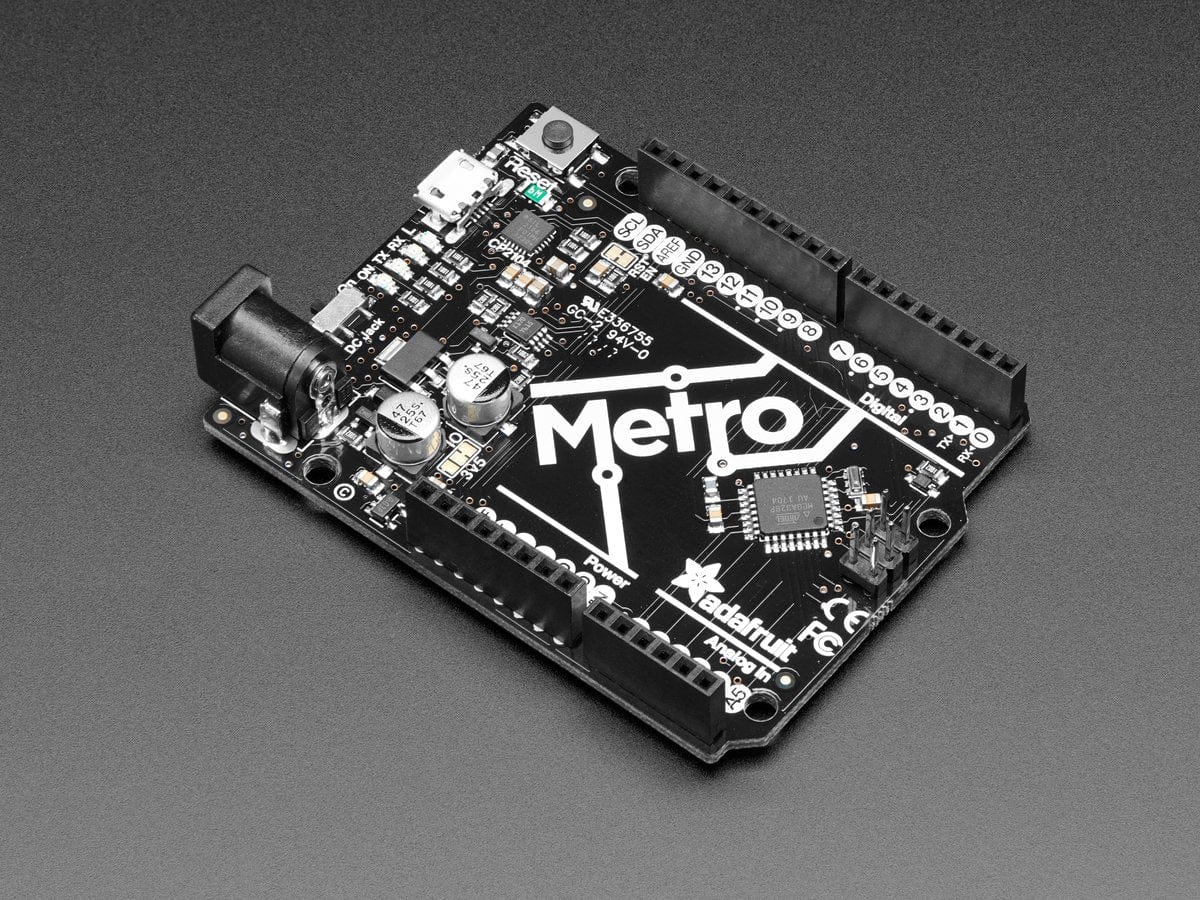
This is the Adafruit METRO Arduino-Compatible – with headers. It’s a fully assembled and tested microcontroller and physical computing board with through-hole headers attached. If you don’t want a Metro with the headers attached for super-slimness, check out our Metro without Headers.
The METRO works great with the Arduino IDE, and runs the ATmega328P at 16MHz so it is shape and pin-compatible with Arduino UNO R3 shields and boards. You can use this with the Arduino IDE (both desktop and cloud version) by selecting ‘Arduino UNO’ in the Boards menu.
We sure love the ATmega328 here at Adafruit, and we use them a lot for our own projects. The processor has plenty of GPIO, Analog inputs, hardware UART SPI and I2C, timers and PWM galore – just enough for most simple projects. When we need to go small, we use a Metro Mini or a Trinket M0, but when size isn’t as much of a concern, we reach for an Adafruit METRO.
METRO is the culmination of years of playing with AVRs: we wanted to make a development board that is easy to use and is hacker friendly. At the heart is an ATmega328P, with 32KB of flash and 2KB of RAM, running at 16 MHz. It comes with the Optiboot bootloader already installed, and is Arduino IDE compatible.
- Power the METRO with 7-9V polarity protected DC or the micro USB connector to any 5V USB source. The 2.1mm DC jack has an on/off switch next to it so you can turn off your setup easily. The METRO will automagically switch between USB and DC.
- METRO has 20 GPIO pins, 6 of which are Analog in as well, and 2 of which are reserved for the USB-serial converter. There’s also 6 PWMs available on 3 timers (1 x 16-bit, 2 x 8-bit). There’s a hardware SPI port, hardware I2C port and hardware UART to USB. Logic level is 5V but by cutting and soldering closed a jumper, you can easily convert it to 3.3V logic
- USB to Serial converter, there’s a hardware USB to Serial converter that can be used by any computer to listen/send data to the METRO, and can also be used to launch and update code via the bootloader
- Four indicator LEDs, on the front edge of the PCB, for easy debugging. One green power LED, two RX/TX LEDs for the UART, and a red LED connected to pin PB5
- Easy reprogramming, comes pre-loaded with the Optiboot bootloader, which is supported by Arduino IDE, and avrdude and only uses 512 bytes – so you have lots of space for your code!
- Arduino IDE compatible, you can use this with the Arduino IDE (both desktop and cloud version) by selecting ‘Arduino UNO’ in the Boards menu.
- Works with all Adafruit shields!
We also include 4 rubber bumpers to keep it from slipping off your desk. Metro shown with our 12x capacitive touch shield attached just to demonstrate the headers, but that shield is not included!
Mac & Windows People! Don’t forget to grab & install the CP2014 VCP drivers from SiLabs to make the COM/Serial port show up right! The default drivers may not support this USB/Serial chip
Technical Details
Detailed specifications:
- ATmega328 microcontroller with Optiboot (UNO) Bootloader
- USB Programming and debugging via the well-supported genuine CP2104
- Input voltage: 7-9V (a 9VDC power supply is recommended)
- 5V regulator can supply peak ~800mA as long as the die temp of the regulator does not exceed 150*C
- 3.3V regulator can supply peak ~150mA as long as the die temp of the regulator does not exceed 150*C
- 5V logic with 3.3V compatible inputs, can be converted to 3.3V logic operation
- 20 Digital I/O Pins: 6 are also PWM outputs and 6 are also Analog Inputs
- 6-pin ICSP Header for reprogramming
- 32KB Flash Memory – 0.5K for bootloader, 31.5KB available after bootloading
- 16MHz Clock Speed
- Compatible with “Classic” and “R3” Shields
- Adafruit Black PCB with gold plate on pads
- 53mm x 71mm / 2.1″ x 2.8″
- Height (w/ barrel jack): 13mm / 0.5″
- Weight: 19g
- Derivative of “Arduino UNO R3 Reference design”
- Open source hardware files on github!
Revision History:
- As of August 31, 2015 we have updated the Metro’s headers to be slightly taller so that they are the same height as classic ‘non-SMT’ headers for a better shield-fit
- As of Oct 12, 2017 we now have fully thru-hole headers instead of SMT headers.
- As of March 30, 2018 we now have swapped the FTDI chip for a SiLabs CP2104
- Pinout Diagram
