Digital Logic Add-On Pack for Kitronik Inventor’s Kit for micro:bit
Learn to think logically with the Digital Logic Add-On for the Kitronik Inventor’s kit for micro:bit!
This kit, along with the Inventor’s kit, serves as an introduction to logic gates and how they can be used in conjunction with the micro:bit. The seven included experiments also cover the Basic Digital Logic curriculum at KS3 (UK Design & Technology curriculum).
Also available: Noise Add-on Pack and the ZIP LED Add-on Pack!
Logic gates are the basic building blocks of digital integrated circuits, the chips found in the majority of electronic products today. Although these experiments explore how individual logic gates work, in chips there could be millions of individual logic gates, depending on the size and complexity of the chip. For example, there are approximately 1.4 billion transistors in a quad-core i7. If we assume that the average gate requires three transistors then that would give approx. 450 million gates.
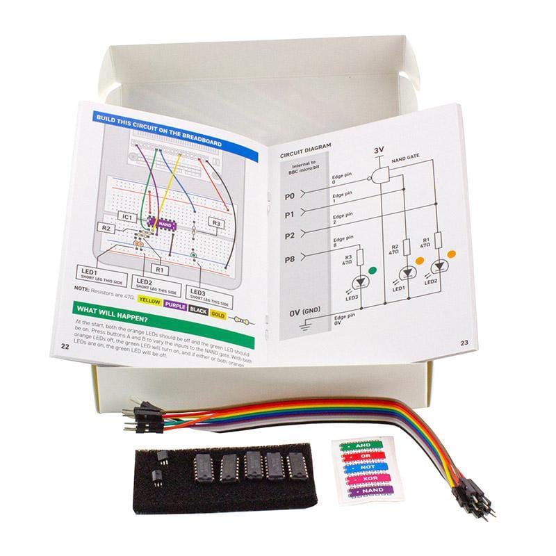
Included in this kit are 5 IC’s, each a different type of logic gate. They are; AND, OR, XOR, NAND, and a NOT Gate. There are also colour coded stickers included, and these colours are used throughout the booklet in the circuit diagrams. The kit also contains 2 x 2N7000 FETs and a pack of 10 male to male jumper wires. Each experiment also makes use of components from our Inventor’s kit for micro:bit, often LEDs as they offer a visual and immediate indication of the ‘state’ of gate inputs and outputs.
The code has been created in the Microsoft MakeCode Editor and the code for each of the experiments can be downloaded from the resources section below. We have also produced Python code examples for each of the experiments, these are also available as a download from the resources section.
Features
- Offers an easy to understand introduction to Digital Logic gates and combining these gates with the micro:bit
- Can be used as a teaching aid for Basic Digital Logic curriculum at KS3
- A fun and hands-on introduction to the building blocks of ICs
- Code can be created with the Microsoft MakeCode editor and also in the Python editor
- Code examples have also been provided as a download from the resources section below. Choose from either blocks or Python.
- Topics covered include; Truth Tables, Semiconductors and state electricity, and how to use gates in conjunction with the micro:bit via code.
- Learn how to build and code the 7 following experiments:
- EXP.1 – Introduction to ‘NOT’ Gates.
- EXP.2 – Introduction to ‘AND’ Gates.
- EXP.3 – Introduction to ‘OR’ Gates.
- EXP.4 – Introduction to ‘NAND’ Gates.
- EXP.5 – Introduction to ‘XOR’ Gates.
- EXP.6 – Half Adder Circuit.
- EXP.7 – Full Adder Circuit With Binary To Decimal Converter.
Contents
- 1 x Quad 2 input AND IC
- 1 x Quad 2 input OR IC
- 1 x Hex NOT IC
- 1 x Quad 2 input NAND IC
- 1 x Quad 2 input XOR IC
- 2 x 2N7000 FET
- 10 x M-M Jumper Wires
- 1 x Set of 5 colour-coded IC Stickers
- Tutorial booklet, containing 7 experiments
Requires
- Kitronik Inventor’s Kit for the BBC micro:bit
- BBC micro:bit
- Micro USB cable
Resources
- MakeCode code examples download
- Python code examples download
Download Notes
- MakeCode – The files have been zipped and will need to be extracted. Once extracted, the files can either be individually loaded directly onto a connected micro:bit or individually dragged and dropped into the MakeCode editor.
- Python – The files have been zipped and will need to be extracted. Once extracted, the files can be individually dragged and dropped into the Python editor. Once in the editor, the file can be downloaded as a hex file that can be dropped directly onto a connected micro:bit.
